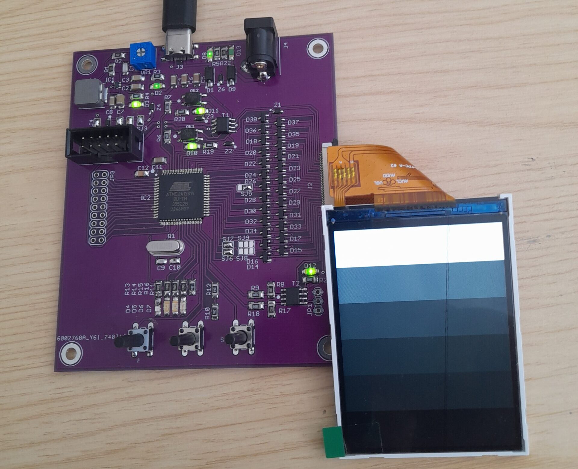
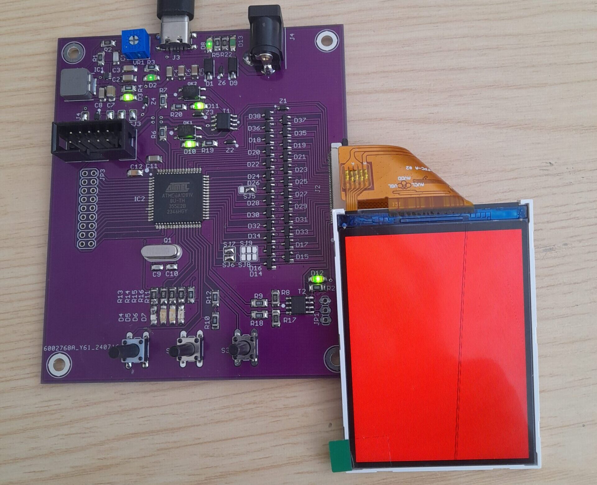
Display Tester
The device is developed for a special display and utilizes Serial 8080 II 16-bit communication. This protocol is more or less universal, so it is possible to connect other types of displays that support it.
The device can be powered by either a 5V or 12V input, with the inputs separated by diodes to prevent damage to the power supply in case both inputs are connected. The power supply voltage is reduced to 3.3V using a step-down converter. The main control chip used is the Atmega 1281V, which has enough memory for potentially more complex patterns. The Atmega is directly connected to the display, so it must be on the same logic level as the display. In this case, this was not an issue. Additionally, the Atmega manages the power control of the display, so it is not necessary to turn off the entire device when replacing the tested display. All data and power pins have protective Schottky diodes that divert any potential static voltage. All power lines have protective Zener diodes to prevent any overvoltage from affecting the system.
The program is written in Bascom-AVR. It is compiled and uploaded using a USBASP programmer. An ISP programming connector is prepared on the PCB. The program contains several test patterns that are generated directly in the microcontroller. Therefore, it was not necessary to store and load an image (BMP). The patterns include a red screen, green screen, blue screen, white screen, black screen, a checkerboard pattern (alternating white and black pixels), grayscale stripes, and a white frame around the edge pixels to check the centering of the display in the opening. According to the datasheet, the Atmega can operate stably at this voltage with an 8MHz crystal. Since this is not for commercial use, I tested a 20MHz crystal. All tests showed no instability. I chose the higher clock frequency for faster loading of the patterns.