DMX LED & Relay Controller
This project was created out of the need to control a decorative Christmas LED light chain using DMX. These LED chains usually have only two wires and are powered by 24V AC. The LEDs are arranged so that the first half lights up during the positive half-wave, and the second half during the negative half-wave. Therefore, it was necessary to design a control system that could independently control both halves of the chain.
I used an H-bridge driver originally intended for DC motors, which allows easy polarity switching on the output and also supports PWM control. DMX slave functionality is implemented using the hardware UART of an ATmega microcontroller, so the CPU isn’t burdened with communication, allowing for very precise PWM control.
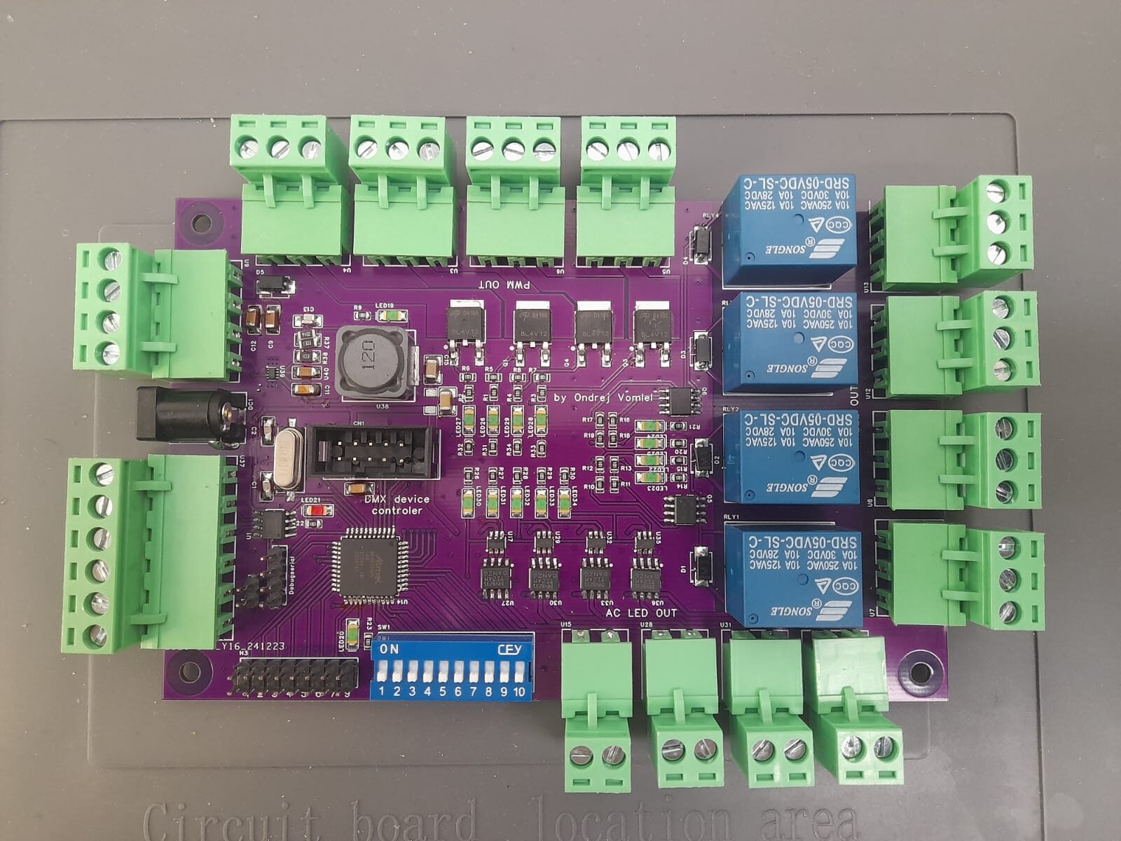
The project is based on the ATmega324PB microcontroller. This MCU offers a large number of PWM channels and other peripherals, which allows the final device to support:
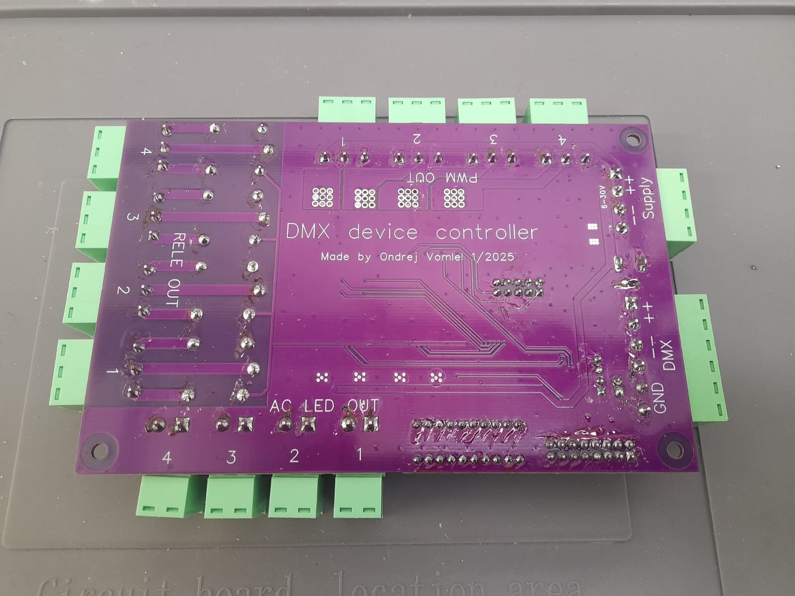
up to 4 outputs for LED chains,
4 PWM outputs for controlling, for example, RGBW LEDs,
4 relay outputs for switching devices like a disco ball motor or non-dimmable lighting.
DMX addressing is handled using a DIP switch. The device uses a total of 13 DMX channels:
Channels 1–4: used to control relays. A value from 0 to 128 turns the relay off, 129 to 255 turns it on.
Channels 5–8: control the PWM outputs. The channel value equals the PWM level – 0 is off, 128 is half brightness, 255 is full brightness.
Channels 9–12: used to control brightness or blinking speed of the LED chains.
Channel 13: selects the operating mode for all four LED chain outputs:
0–25: only the first half of the LED chain lights up,
26–50: only the second half lights up,
51–150: alternating blinking mode (LEDs are fully on and channels 9–12 change function from brightness to blink speed control),
151–250: alternating blinking with gradual fade-in and fade-out,
251–255: LEDs are continuously on (both halves rapidly alternate); channels 9–12 again control brightness.
The controller can be powered with a voltage in the range of 6–35 V. The supply voltage is directly applied to the LED chain outputs, so using a 24V power adapter with sufficient current capability is ideal.
During development, I encountered several challenges with using timers for PWM outputs. It turned out that when a timer is used for PWM, other pins associated with that timer cannot be used for different functions, such as interrupts (INT). As a result, the debug serial output is not available in this version.