Tester for buttons and LEDs
I created this project at my job. The request was to replace the test equipment with buttons and add an LED inspection function.
The device is capable of testing switch buttons by detecting the pressed button, measuring the resistance, and checking for any other pins connected to the button. In the settings, the polarity for testing the button can be set. This can be useful when buttons are connected in series with a diode. The device also checks for duplicated or other pins. Certain pins can be excluded from the test, and it can measure constant resistance between pins, if desired.
Additionally, the device can test LEDs in two ways. The first method is an ESD test that sends a current of 100uA into the LED and checks its loss, which should not be lower than, for example, 2V (determined by the type and quantity of LEDs in series). The LED is also tested for higher currents (1, 5, or 10mA), and the voltage drop on the LED is measured. The value should not exceed, for example, 3.5V (determined by the type and amount of LEDs in series). A higher voltage could potentially cause high resistance in the conductive paths, a cold connection, or a damaged LED.
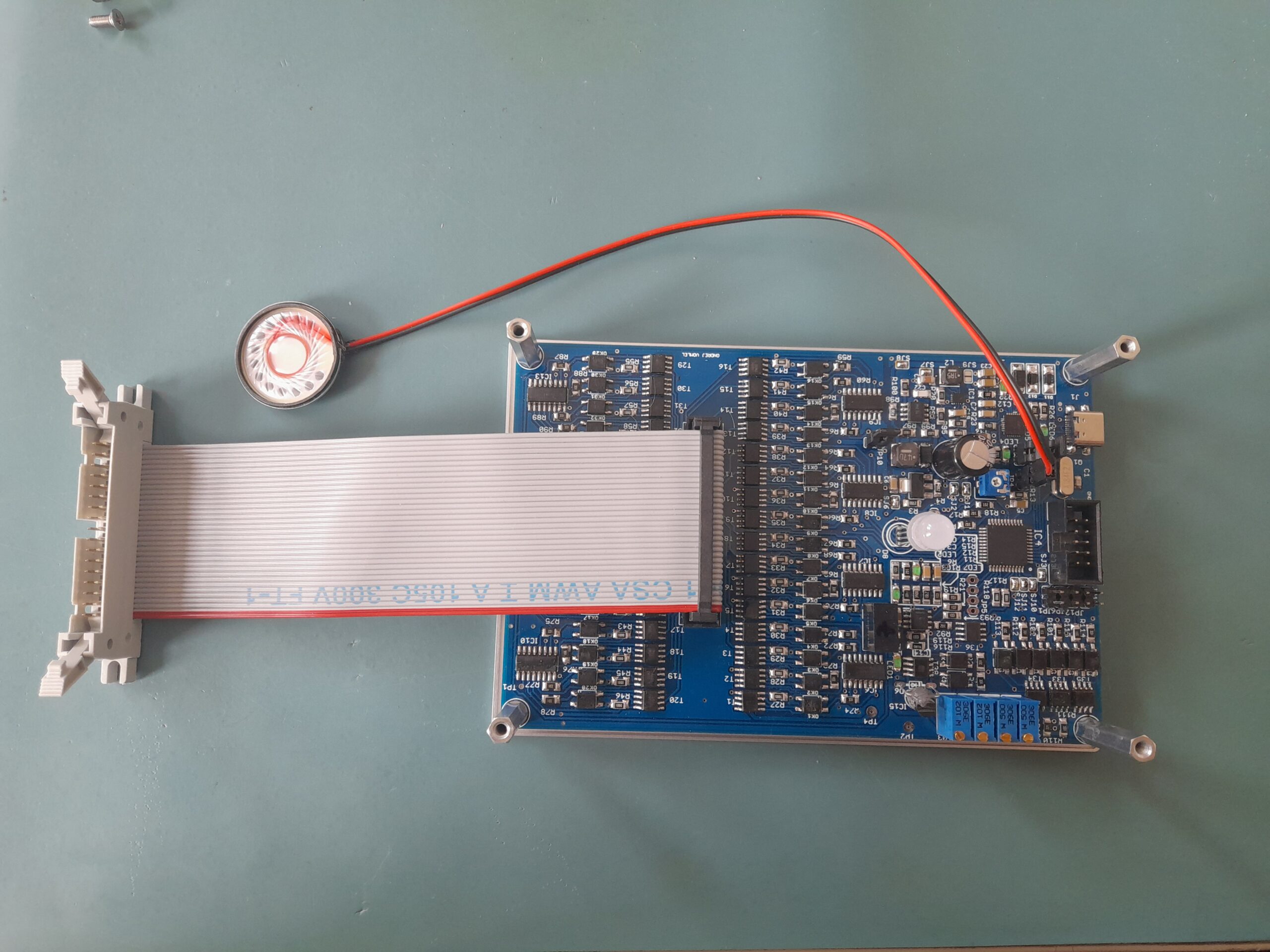
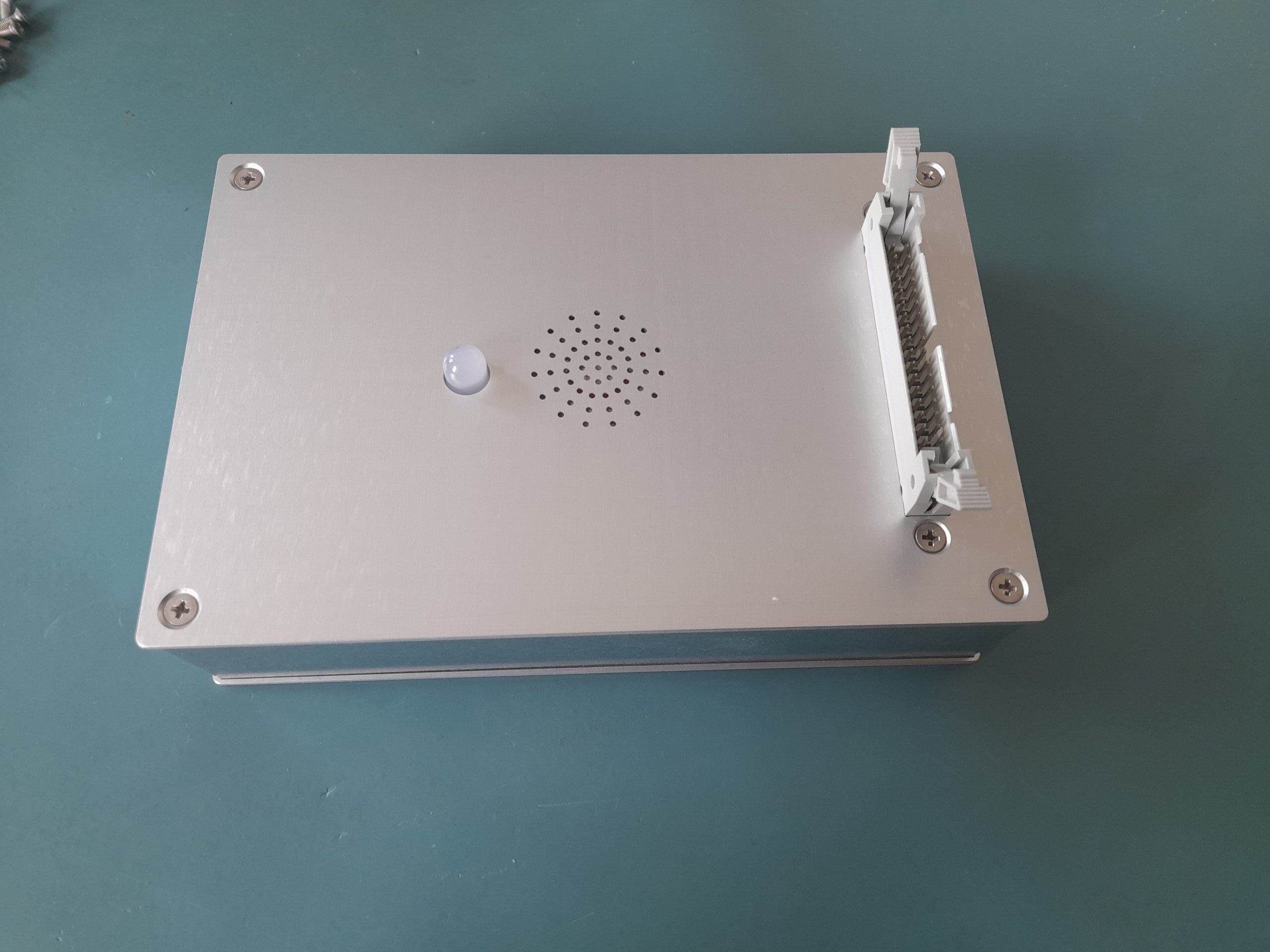
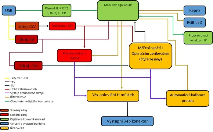
The device uses a USB-C connector for communication and power. The voltage from the USB is converted to 5V and approximately 35V using two switch sources. From the 5V, a separate DC-DC converter generates -3.3V to power the operational amplifier. The 35V voltage is reduced to 31-33V through a linear stabilizer to eliminate noise. A current source with LM334 controls the 31V voltage, limiting the current to either 100uA, 1mA, 5mA, or 10mA. The current value is adjustable using trimmers on the PCB. The selected current limit is determined by the MCU. The limited voltage is distributed to 32 half-H bridges, determining the destination of the pin (+ or -). The H bridges consist of N-type FETs with the „upper“ transistor controlled by an optocoupler with a photodiode. This setup allows for the use of N-type FETs. The „bottom“ transistor is driven directly. Since the MCU does not have 64 outputs (requiring two signals for each output pin), control signals are generated using eight shift registers (74HC4094D) controlled by only three MCU pins: signal, clock, and enable. The device includes automatic current calibration, compensating for the temperature dependence of the LM334 (partly compensated by the diode connection). This allows the MCU to accurately calculate the current flowing through the component under test and determine its resistance. Four ADC converters from the MCU are used to measure the loss, each with a different range of measured voltage created by an operational amplifier and resistor dividers (ranging from 0-0.1V to 0-30V). This enables the device to measure voltage and calculate supports with a maximum accuracy of 1%. The MCU (Atmega 1284p) controls the entire measurement, control, and output switching process. The program is uploaded to the MCU using the ISP connector and the USBasp programmer. The MCU communicates with the computer through a USB/RS232 converter (CP2102) at a BAUD rate of 115200. This converter is fully compatible with Windows, Linux, Android, and possibly IOS (not tested) operating systems. The device incorporates an RGB LED and a speaker to indicate the measurement status.
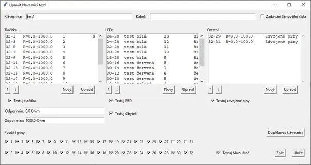
A PC program has been developed for the device, written in the Python language. The program enables USB communication with the device, handles measurement input, displays measurement progress, and saves the results. The hardware itself is not functional as a standalone device, but it can be interacted with through the console by entering specific commands. The communication protocol between the PC program and the device is not encrypted. The program can be executed on a PC without connectinng the device, but its functionality is limited to creating and editing measurement data.
The PC program was created by my friend Jiří Štěpanovský at www.jiristepanovsky.cz.